
Every machined part drawing is a negotiation between what the function needs and what the process can hold, and if you understand that negotiation, you get parts that work at a price that makes sense. Tolerance and surface finish are where that negotiation happens: too loose and the part does not function, too tight and the price rises for no reason. On 4-axis CNC milling the picture has one extra layer, because the rotary axis changes how relationship tolerances behave — a feature that crosses two faces is held in one setup instead of two, which is exactly the kind of tolerance that causes arguments on machined parts. This article explains what tolerance and finish values actually mean on the shop floor, what a well-run 4-axis shop can hold, and how you verify the claim instead of trusting it.

What does ±0.003 mm (milling) / ±0.002 mm (turning) really mean on a machined part?
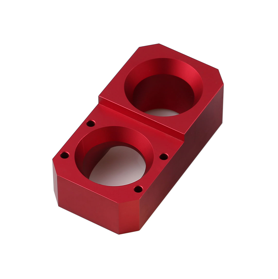
Start with the scale. A human hair is roughly 0.07 mm across; ±0.003 mm (milling) / ±0.002 mm (turning) is less than a tenth of that — about five micrometres either side of nominal, ten micrometres total window. That is the working capability envelope for controlled milling and turning features on a disciplined shop: holes that must locate a mating pin, bores that carry a bearing, press-fit diameters where a micrometre changes the assembly force. When a supplier tells you its process holds ±0.003 mm (milling) / ±0.002 mm (turning), it is describing what the process does on controlled features with proper tooling and measurement, not what every surface on every part automatically gets.
Two qualifications matter to a buyer. First, a tolerance applies where the drawing says it applies, and only there. A drawing that carries a general tolerance note of ±0.1 mm and one critical bore at ±0.002 mm is a normal engineering document; a drawing that implies everything is tight is a drawing that will be expensive or ignored. Second, tight tolerance is not free — it costs in tooling, inspection time, and scrap rate, and the cost curve steepens as the band narrows. The economical drawing is the one where the ±0.003 mm (milling) / ±0.002 mm (turning) callout appears only on the features that actually need it.
Which tolerances can a 4-axis CNC milling process actually hold?
The honest capability statement for a precision CNC shop runs on two process families. Milling and turning hold ±0.003 mm (milling) / ±0.002 mm (turning) on controlled features, which covers the great majority of machined geometry — drilled and reamed holes, milled pockets, turned diameters, and faces. Where a feature demands more, precision grinding reaches ±0.002 mm, and that is a separate operation with its own setup, its own machine, and its own inspection. The process capability target on critical characteristics is Ppk ≥ 1.67 initial, which is the statistical statement behind the tolerance: the process is centered and stable enough that parts stay inside the band with margin, not just at the edge of it.
For you, the practical version of this is a question to ask at quoting: which of my features sit in which band? A bore that must seal against an O-ring or carry a bearing sits in the controlled milling band, verified on a CMM. A ground journal or seal diameter that needs ±0.002 mm is a grinding operation and should be quoted as one, with the extra process step visible in the price and the lead time. A supplier that quotes every feature at one tolerance regardless of what the drawing says is either overcharging you or under-delivering — the drawing should drive the band, not the brochure.
Why does a 4-axis machine change the tolerance story?
The rotary axis matters most for relationship tolerances — the ones that connect features on different faces of the same part. Picture a bracket with a mounting face on one side and a bore on the other: on a 3-axis machine the part is clamped, machined, unclamped, re-clamped, and the bore is machined in a second setup. The bore's position now depends on how accurately the second setup found the datums of the first, and that error stacks onto everything else. On a 4-axis machine with the part indexed on the rotary axis, both features are machined in one clamping, so the relationship between them depends only on the machine's own accuracy, which is repeatable and measurable.
That is why 4-axis work is not only about saving setup labor; it is about holding tolerances that are genuinely hard on multiple setups. When you review a drawing of a multi-face part, find the characteristics that cross faces — the bore whose true position is referenced to a face on the other side, the two holes whose center distance is critical across an angle — and ask whether they will be machined in one setup. The answer decides whether the tolerance is comfortably held or fought for, and it belongs in the quote. The services page of this site describes how indexed and simultaneous 4-axis work is planned around those relationship features.
How should tolerance be expressed on the drawing?
Numbers without a reference system are where tolerance disputes start. A ±0.002 mm bore that is measured from three different datums by three different people will produce three different answers, and all of them can be defensible. That is what geometric dimensioning and tolerancing, or GD&T, exists to prevent: it defines the datum reference frame, the tolerance zone, and the meaning of the callout so that the shop, the inspector, and your receiving department measure the same thing. On a part with critical features, express them with GD&T against explicit datums rather than as bare coordinate tolerances, and let the general note carry the rest.
Two more details keep the drawing honest. State the reference temperature, because dimensional measurement references 20 °C and metal moves with temperature — aluminum expands about 23 micrometres per metre per degree Celsius, so a long feature measured warm will disagree with the same feature in a temperature-controlled lab. And state which instrument class verifies the tight features, because measurement resolution is arithmetic: an instrument should resolve roughly ten times finer than the band it judges, so a ±0.003 mm (milling) / ±0.002 mm (turning) feature belongs on a CMM rather than a hand-held gauge. Agreeing the datum scheme, the reference condition, and the instrument before the first batch removes nearly all the arguments that happen after it.
What do surface finish numbers actually mean?
Surface finish is expressed most often as Ra — the arithmetic average deviation of the surface profile from its mean line, in micrometres. Lower Ra is smoother, but the numbers only mean something relative to how they are made. A machined surface after normal finishing passes typically lands around Ra 1.6 µm; finer values come from dedicated finishing operations, and grinding or polishing can take a surface well below that. Your job is to specify the Ra the function needs — a sealing face, a bearing seat, or a surface that slides against another part has a real finish requirement, while a hidden pocket wall has none — and to resist the habit of ordering the finest finish on every face, because each step down the Ra scale adds process time and cost.
Match the finish to the process family when you specify it. A finish that needs grinding should be on the drawing as a ground surface, not left for the shop to discover after milling. A finish that needs polishing after machining should be called out with the area it applies to, because polishing is a hand or semi-automated operation that touches only the surfaces you mark. And keep the machined finish separate from any coating requirement in your mind and on the drawing: anodizing, plating, and passivation change the surface after machining, so the Ra before coating and the requirement after coating are two different specifications, and the shop needs to know both.
How should finish be specified so it can be verified?
A finish callout that cannot be measured is a decoration. Name the parameter and the value — Ra 1.6 µm — and say where it applies, and if the direction of the surface lay matters, add it, because a seal can leak along a spiral lay even at a good Ra value. On critical surfaces, ask how the finish will be verified and with what instrument; a proper shop measures finish with a profilometer or a surface roughness tester and reports the value, not a "good finish" comment on an inspection form. Put the finish check in the first article alongside the dimensions, because a finish problem discovered after anodizing is a rework problem with a coating already on it.
Where finish and tolerance interact, the drawing should say which governs. A ground surface carries both a size tolerance and a finish, and grinding achieves both in one operation, but polishing a surface to a mirror Ra can round a sharp corner or open a size, so a polished sealing diameter needs its size tolerance protected in the callout. The rule for you is simple: state the value, state the location, state the method if it matters, and verify it on the first article. The quality page of this site describes the inspection instruments and reporting the shop applies to finish and geometry checks.
Which common tolerance and finish mistakes inflate part cost?
Most cost overruns on machined parts come from specification habits, not from the shop. The most common is over-tolerancing everything: a drawing covered in ±0.003 mm (milling) / ±0.002 mm (turning) callouts where the function needs one critical bore and a general note for the rest. Each unnecessary tight callout adds inspection time and scrap risk across the whole run. The second is mixing up finish and tolerance intent, like specifying a fine Ra on a surface that will be anodized anyway, where the coating will dominate the final surface. The third is leaving finish off the drawing entirely and discovering at the sample stage that "machine finish" means something different to you and to the shop.
The fourth mistake is 4-axis-specific: ignoring how many setups the tolerance implies. A relationship tolerance across two faces that the shop plans to machine in two setups will cost more in scrap and rework than the same tolerance machined in one setup on a rotary axis, or it will be quietly loosened in practice. When you review a quote, check that the setup strategy matches the tight features on the drawing. If a part is genuinely multi-face with crossing tolerances, routing it to a 4-axis machine is often the cheaper way to hold the drawing, not the more expensive one. The parts and materials range on the parts page of this site shows the kind of geometry this applies to.
How does a buyer verify that a tolerance or finish claim is real?
Verification comes down to one habit: asking for evidence on a named characteristic rather than accepting a general capability claim. For a critical dimension, ask for a CMM report listing the nominal, the actual, and the deviation for that specific feature. For process stability, ask for SPC data — a control chart naming the characteristic, the tolerance band, and the subgroup count — with a capability figure computed from it, against the target of Ppk ≥ 1.67 at the initial study on critical characteristics and Cpk ≥ 1.33 on general characteristics. Capability is reported per characteristic: every report names the feature, its tolerance band, the sample size, the sigma method, and the study window. For surface finish, ask for the measured Ra value and the instrument that measured it, on the first article and on the production sample.
Two checks keep the evidence honest. First, make sure the instrument matches the feature: a caliper cannot resolve a ±0.002 mm bore any more than a hand magnifier can read a serial number at 20 paces, and a report that lists only a hand gauge for a tight feature has already told you the truth about the measurement. Second, check the numbers against the process: a shop that reports every dimension at exactly nominal on every part has either a spectacular process or a form that was filled in, and a first article that flags a non-conforming characteristic for disposition is more believable than one that never finds anything. Evidence that names the feature, the instrument, and the value is the evidence you can act on.
What is the practical tolerance and finish checklist for a 4-axis order?
Condense everything above into a short list to run against any drawing before it goes out for quote.
- Tolerances by function: Mark the features that genuinely need controlled tolerance — ±0.003 mm CNC milling, ±0.002 mm CNC turning, ±0.002 mm grinding — and let a general note carry the rest.
- Datum scheme: Define the datums and express critical features with GD&T so everyone measures the same part.
- Setup strategy: Confirm the features that cross faces will be machined in one setup on the rotary axis, and that the quote reflects it.
- Finish values: Name the Ra value and location for the surfaces that need it, and separate machined finish from coating requirements.
- Measurement: State which instrument verifies the tight features, and require CMM or profilometer data on the first article.
- Reference conditions: Agree on 20 °C as the measurement reference so a warm floor and a metrology lab do not argue with each other.
Tolerance and finish are where the drawing meets reality, and on 4-axis CNC milling the reality is good — the capability is there, and the rotary axis genuinely helps hold the multi-face relationships that other processes fight. What separates a part that works from a part that argues is specification discipline: tight where it matters, loose where it does not, measured where it counts, and verified on the first article. Apply that discipline once, and every later batch inherits it.
your rule of thumb: on machined parts, tolerance and finish cost money in proportion to how much of the drawing they cover. Put them where function needs them, define how they are measured, and verify the first article — the rest of the drawing can stay comfortably loose.
What this shop actually runs
Capability evidence should come as specifics, not slogans. Behind this guide is a 6,800 m2 plant in Dongguan, China running 100+ CNC machines with 100+ staff. The machine list by category:
- 5-axis machining centres (10+) - Mazak VARIAXIS I-600 (510/910/510 mm travel, 12,000 rpm, 22 kW, 71.6 N·m, 30-tool BT40) and Mazak INTEGREX I-250H S (B-axis 0.0001°, 24 kW, 124 N·m, 38-tool HSK-A63). Best for compound-angle parts, single-setup multi-face prismatic work, and aerospace fittings where datum transfer loss is unacceptable.
- 3-axis / 4-axis machining centres (50+) - Brother SPEEDIO S500Z2N / S700Z2N (10,000 rpm, 14/21-tool ATC, 0.7 s tool-to-tool, Z-axis 2.2 G) and Mazak VCE-430A L / VCE-570C L (10,000 rpm, 118 N·m, 24-tool ATC). Best for prismatic parts, plates, brackets, housings.
- Swiss-type turning centres (10+) - Citizen Cincom A20-3F7 (Φ20 mm, 10,000 rpm), TSUGAMI B0206-III / B0205-III (Φ20 mm, 0.1 µm), STAR SR-32JII / SR-32J Type N (Φ32 mm, 8,000 rpm). Best for long, slender rotational parts at ±0.002 mm.
- CNC turning centres (20+) - HEADMAN T70M/1250 (720 mm swing, 117 mm bore, 3,000 rpm, BMT75 12-station turret). Best for shafts, bushings, flanges up to ±0.002 mm.
- Wire EDM (5+) - Sodick AQ535L (550/350/300 mm travel, ±20° taper, 800 kg workpiece). Best for hardened tool steel, internal splines, sharp internal corners that milling cannot reach.
- Inspection: Hexagon CMM + 20+ gauges - Hexagon CMM for coordinate measurement, plus vision system, profilometer, hardness tester, coating thickness gauge, XRF for material verification. The 10:1 rule (gauge 10x more accurate than the band) is applied to every feature.
- Machine highlights - VARIAXIS I-600: one-setup multi-face 5-axis + MAZA-CHECK auto-calibration; INTEGREX I-250H S: DONE-IN-ONE mill-turn, B-axis 0.0001° + Ai thermal shield; SPEEDIO S500Z2N / S700Z2N: Z-axis 2.2 G + 0.7 s ATC; Swiss-type: guide-bush switchable + 0.1 µm resolution.
Tolerance: ±0.003 mm CNC milling / ±0.002 mm CNC turning / ±0.002 mm grinding and wire EDM. Capability: Ppk >= 1.67 initial on key characteristics, Cpk >= 1.33 ongoing.
Certificates: ISO 9001:2015 (116024/A/0001/UK/En), IATF 16949:2016 (131941/A/0001/SM/En, with design clause 8.3 excluded, stated openly) and ISO 14001:2015 (116024/B/0001/UK/En), issued to Dongguan Zhuohang Ltd, registration 91441900MA4UWT6X39, founded 2005.
Where we ship: Austria, Belgium, the Czech Republic, Denmark, France, Germany, Greece, Hungary, Ireland, Italy, the Netherlands, Spain, Sweden and the United Kingdom in Europe; Brazil, Canada, Mexico and the United States in the Americas; China, Israel, Japan, Singapore and Sri Lanka in Asia; Australia and New Zealand in Oceania; and South Africa in Africa — plus other countries and regions worldwide, shipped from our base in Dongguan, China.
Contact: Felipe Iglesias, [email protected], +86 13126536955.
Need a drawing reviewed for realistic tolerance and finish callouts?
Send the drawing through the contact page — the DFM review will come back with the features that can stay loose, the ones that need controlled tolerance, and how each critical surface will be measured.
Frequently Asked Questions
What is the tightest tolerance a 4-axis CNC milling shop can hold?
In short, Milling and turning hold ±0.003 mm (milling) / ±0.002 mm (turning) on controlled features, and precision grinding reaches ±0.002 mm, with process capability Ppk ≥ 1.67 at the initial study on critical characteristics and Cpk ≥ 1.33 on general characteristics. Capability is reported per characteristic: every report names the feature, its tolerance band, the sample size, the sigma method, and the study window.
What surface finish can standard CNC milling achieve?
In short, A machined surface typically lands around Ra 1.6 µm after finishing passes, with finer results available through dedicated finishing, grinding, or polishing. Specify the Ra the function needs and ask how it will be achieved, rather than ordering the finest finish on every face.
Is a tighter tolerance always better?
No. The cost curve steepens sharply as the band narrows, because tooling, inspection time, and scrap rate all rise. The economical drawing puts tight tolerance only where function needs it and leaves the rest to a general note.
How does a 4-axis machine help hold tolerance?
In short, The rotary axis machines multiple faces in one clamping, so relationship tolerances between features on different faces are produced against one datum relationship instead of stacking across two setups. That removes re-clamp error, which is why crossing-face tolerances are often more reliable on a 4-axis machine.
How should I specify a surface finish on a drawing?
In short, Name the parameter and value — for example Ra 1.6 µm — and state where it applies. Add lay direction or a local note where it matters, and keep machined finish separate from any coating requirement, because anodizing or plating changes the surface after machining.
How do I verify a tolerance claim from a supplier?
In short, Ask for measurement evidence on a named characteristic: a CMM report listing nominal, actual, and deviation for the feature, or SPC data showing process capability at Ppk ≥ 1.67 initial. An instrument should resolve roughly ten times finer than the band it judges, so a ±0.003 mm (milling) / ±0.002 mm (turning) feature belongs on a CMM, not a hand gauge.
Continue reading: What Tolerance Can 4 Axis CNC Milling Hold · Medical 4 Axis CNC Milling · What Is 4 Axis CNC Milling
Standards referenced on this page
- ASTM B211/B211M-19 — Standard Specification for Aluminum-Alloy Rolled or Cold Finished Bar, Rod, and Wire
- ASTM A582/A582M-12 — Standard Specification for Free-Machining Stainless Steel Bars
- ISO 9001 — Quality management systems — Requirements